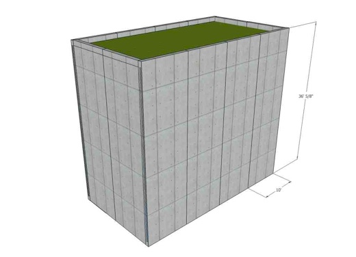
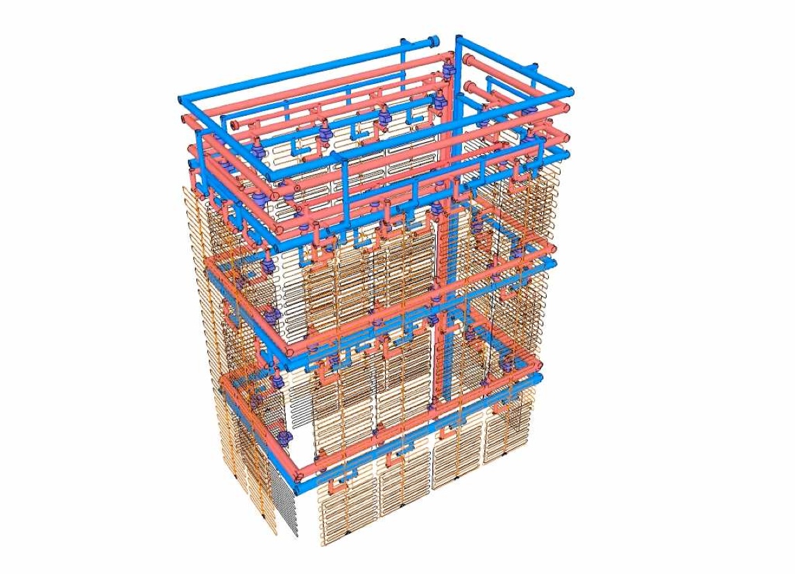
The house is a huge heat exchanger. A total of 12 insulated prestressed concrete panels form the walls that are partially below grade (window and door openings are omitted here).


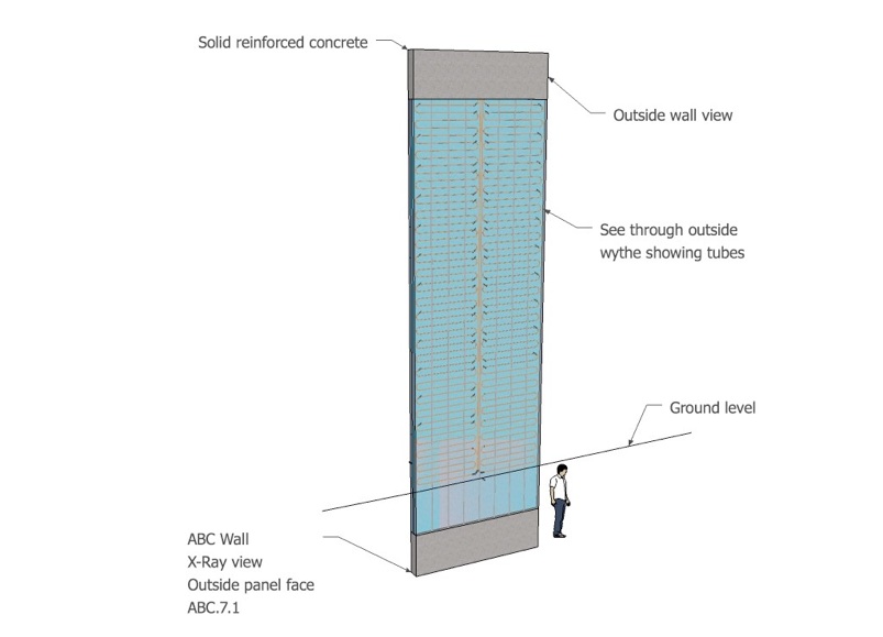
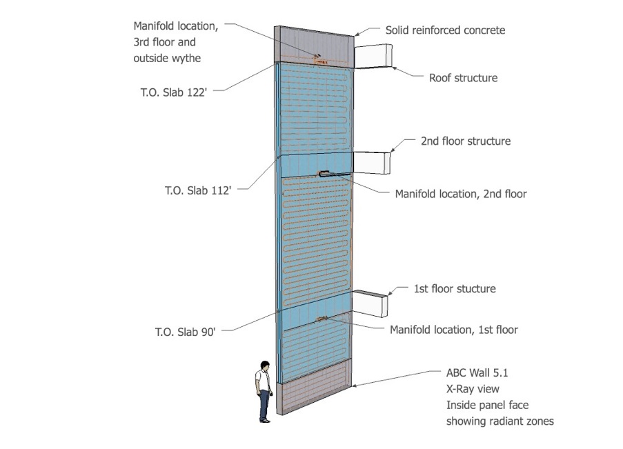
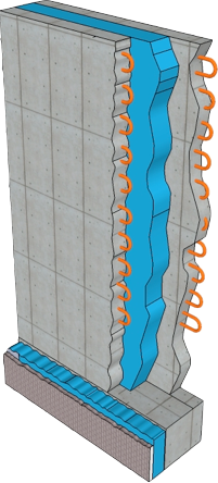
Prestressed concrete walls have heat exchanger tube arrays in the outside and inside wythes, separated by insulation. The top of each wall is a solid piece of concrete, for structural reasons.
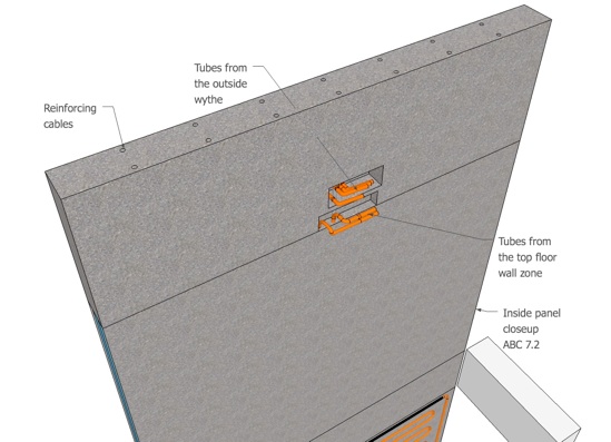
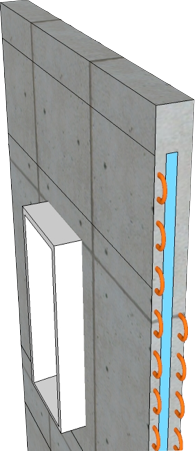
This detail shows how the pipe ends can be hidden in a cavity during the concrete pour.
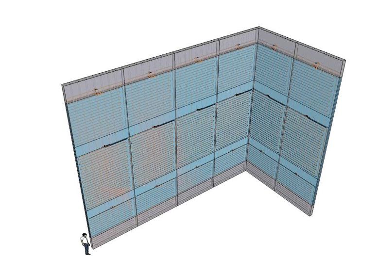
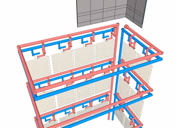
This view shows 6 inside wall panels with each floor isolated.

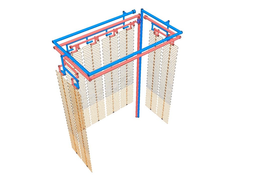
Here’s an artistic concept for the supply and return piping to supply both heated and chilled water to the interior zones on each floor. The risers are actually located in two interior chances and the horizontal piping is located in the ceiling above acoustical ceiling panels.
Overview:
Water to water (ground-source) heat pumps and ground-coupled heat exchangers are a mature technology for space conditioning in commercial and residential buildings. Although we have the land in our project to do exactly that, we are concerned that over time, ground temperatures rise (or fall) through the course of a season leading to performance drops. In many projects, land is simply not available to install a ground loop or to drill down to ground water sources.
Our alternative is a novel Active Building Coupled (ABC) heat exchange system. These are specially built insulated prestressed concrete walls with heat exchange tubing (and someday phase change materials) embedded to provide space conditioning and domestic hot water preheat.
U.S. Patents applied for and pending.
The ABC walls are coupled with a small high efficiency water x water heat pump from HydroTemp. Each wall section is made of a three inch thick outer concrete wythe, polyisocyanurate insulation core, and a three inch inner concrete wythe. 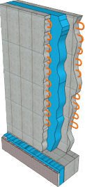 Both inner and outer wythes will have Cross linked Polyethylene (PEX) heat exchangers embedded to collect, transfer and emit energy. Walls will operate as separate, but coordinated systems to absorb and radiate energy both inside and outside the building envelope.
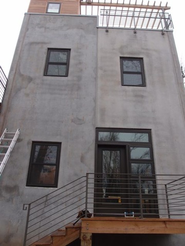
The house is in effect, a three story heat exchanger oriented south and designed to use a weather responding envelope to establish new standards in energy efficiency and comfort. The house has a 20’ x 40’ footprint made up of 10’ wide by 37’ tall panels welded together to form a well insulated, low maintenance package that also resists fires, tornados, termites and falling trees. The energy to operate the heat pump, circulators and valves is mostly provided by a photovoltaic array on the nearby shop roof.
The panels:
Prestressed panels were factory assembled in Springfield by Prestressed Casting Company. Overall wall thickness is 10”. In addition to holding 2 miles of PEX heat exchange tubing, the concrete wythes are structurally reinforced with embedded prestressed steel cables, steel rebar and steel mesh. These walls form the walk-out basement as well as the upper floors. 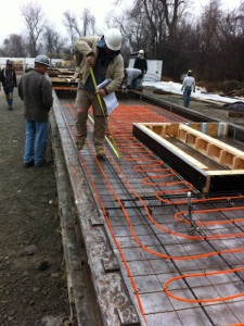
http://www.prestressedcasting.com/
The piping:
During assembly, 3/8” I.D. PEX tubing was secured to steel mesh on 8” centers. The manifolds for each PEX circuit were located in plastic wall boxes above each floor for easy access and to prevent airlock in the circuits. For the outer walls, we located one manifold box at the top of each wall.
Supply and return piping comes from the mechanical room in the basement to serve the outer walls and all the interior walls in each floor. This piping is located in two mechanical chases on the north side of the building.
The Phase Change future:
Someday, we hope to minimize the thickness of the outer wythe to encourage faster response to a changing outside environment. In order to avoid large thermal storage tanks, however, we want the inner wythe to store as much energy as possible within a human comfort range. That’s why we will plan to embed sticks of PEX with phase change material with permanently seal caps. These sticks will be secured to the heat exchange modules between runs of piping.
Design issues:
Here are a few design questions we hope to answer:
a. How well will the ABC walls absorb energy from the sun throughout the year and how they will act as Black Body radiators to reject energy from north facing surfaces during air conditioning months? See this link for an article in the April 2010 SolarPro magazine that makes a case for replacing traditional solar water storage tanks with carefully distributed energy storage throughout the mass of a house.
b. How well will an unglazed walls/heat pump combination meet our DHW needs on a seasonal basis?
c. How well will the inside walls will work for both radiant heating and radiant cooling? Will supplemental radiant surfaces or other technologies will be required? Specifically, will we need radiant floors to supplement the radiant walls? What is the best way to deal with the summer latent heat load?
d. Will the Climate Automation control technology manage fluid flows through heat exchangers in both wythes when coupled with outside/inside sensors to optimize the COP of the heat pump? We need to minimize condensation on the walls during the radiant cooling season and deal with the lag associated with a very high mass building/mechanical system. A control that can anticipate weather conditions from on-line sources and can learn from experience to fine tune the performance of the whole system like ENV from Climate Automation looks like the ideal solution.
e. We are designing a mechanical schematic for HVAC/solar/radiant system. Because our plan is for a Net Zero Energy home, we will be deriving much of our energy from a PV array. The energy draw of the mechanical panel needs to be optimized with high efficiency permanent magnet motor equipped circulators and low energy-draw actuator valves. The ABC Wall is a dynamic solution to space conditioning, but we will emphasize elegant design and serviceability.
Solar orientation:
A very significant amount of heat is delivered by the sun on south facing walls in January. 3 to 4 kwh/m2 of radiation is available in January in the Midwest, more in many other areas.
If a south facing wall is able to harvest only 10% of the incident solar energy that impacts the wall in January, then 300+ watts will be available, or about 1,000 BTU/Day. An average modern home has a maximum heat loss of about 30 Watts/ Hr/square meter (approx. 100 BTU/H), or about 750 Watts/Day/square meter (approx. 2400 BTU/Day) under design conditions. (NREL Solar Map)
Assuming no heat gain from east or west walls, and no heat harvested from ambient air temperatures, one square meter of vertical south facing wall could provide the energy, when coupled to a water- water (or water-air) heat pump to heat 4 or more square meters of floor area under the maximum expected heat loss conditions. At a 20% efficiency, one square meter of vertical wall could heat 8 meters of floor area per day.
These high mass walls add thermal stability and the ability to offset cooling requirements to off-peak hours.
Inside detail showing how the rooms are divided by manifolds. We control both sides of each panel by room zones inside and whole walls outside.
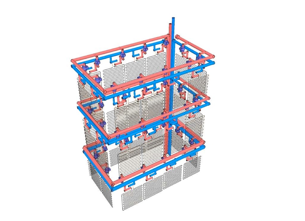
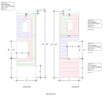
Inside zones, showing all floors
Outside zones, detail
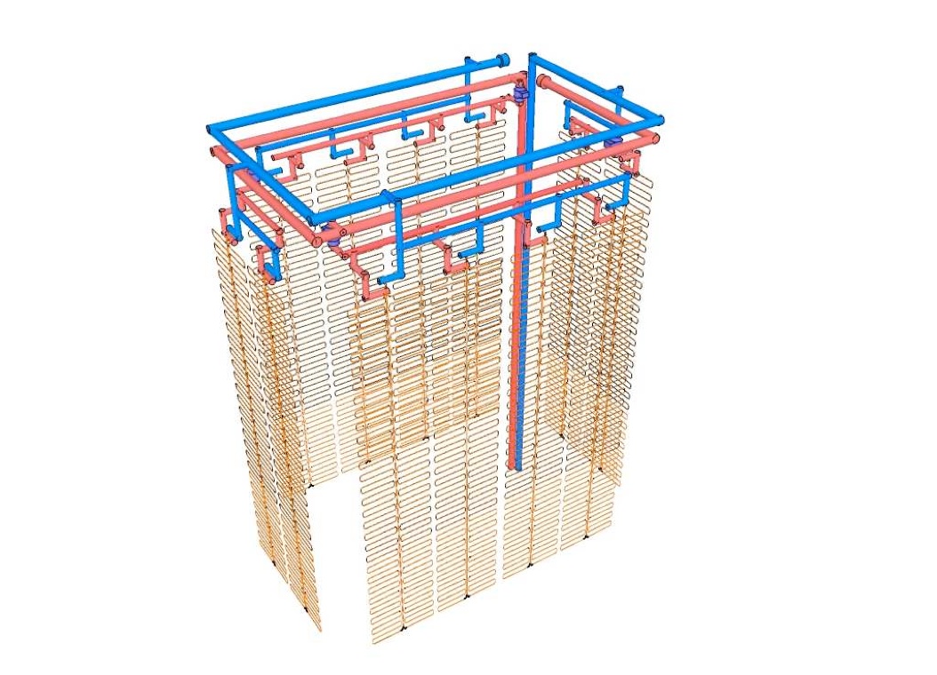
Outside zones, showing all walls
All walls and zones, inside and outside.
Inside zones, detail


* * *

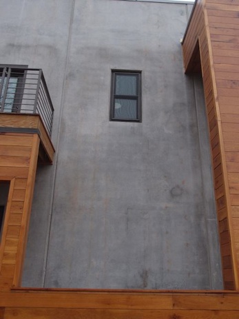
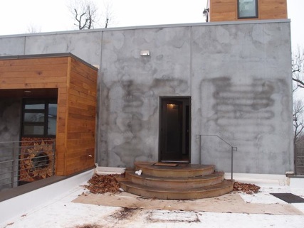

In early December, 2012 we were experimenting with our outer walls to get more energy for space heating. We opened up the North walls one evening when outside temperatures dropped to the high 30’s. Super-chilled water/antifreeze extracted energy from the outer concrete wythe and caused condensation to form the next morning.